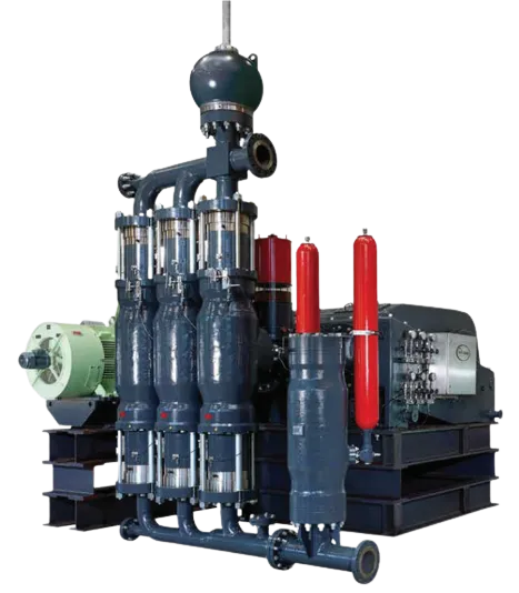
Multisafe Double-Hose Diaphram Pumps
Multisafe Double-Hose Diaphram Pumps covers various options and applications. View our products below or download our PDF brochure
Ready To Get Started?
Members Of The Arc Flow Group
Welcome to Feluwa
Who Are We ?
FELUWA Pumpen GmbH has at its base in excess of 100 years‘ corporate history. In 1901, the parent company was established in Neuwerk/Mönchengladbach as a foundry and expanded in 1931 by the addition of a machine factory, based in Cologne. At that time, the company focused on the production of equipment of fire, air and water technology.
The company name FELUWA is de- rived from the German words for the former business operating areas “fire” (FEUER), “air” (LUFT) and “water” (WASSER).
After a relatively short period of time, the company started concentrating on pump technology. In 1960, the company moved to Mürlenbach in the Eifel area. The integration of FELUWA Pumpen GmbH into the ARCA Flow Group in November 2000 provided the opportunity for further global growth. For in excess of 80 years, ARCA Regler GmbH has been one of the leading manufacturers of control valves, pneumatically activated actuators and positioners. With a diverse range of control valves, pumps and level indicators the ARCA Flow Group is firmly established in various fields of operation, such as chemical, petrochemical, power plants and synthesis gas plants, oil and gas, mining, food industries.
The continuous process of innovation and development of FELUWA Pumpen GmbH has been subject to multiple high-ranking recognition and awards.
The total company land area exceeds 100,000 m2, including more than 9,350 m2 of building area for production and office facilities. FELUWA is continuously expanding and investing in new machinery and production halls in order to ensure constant and
optimum quality standards.
Why hose-diaphragm pumps?
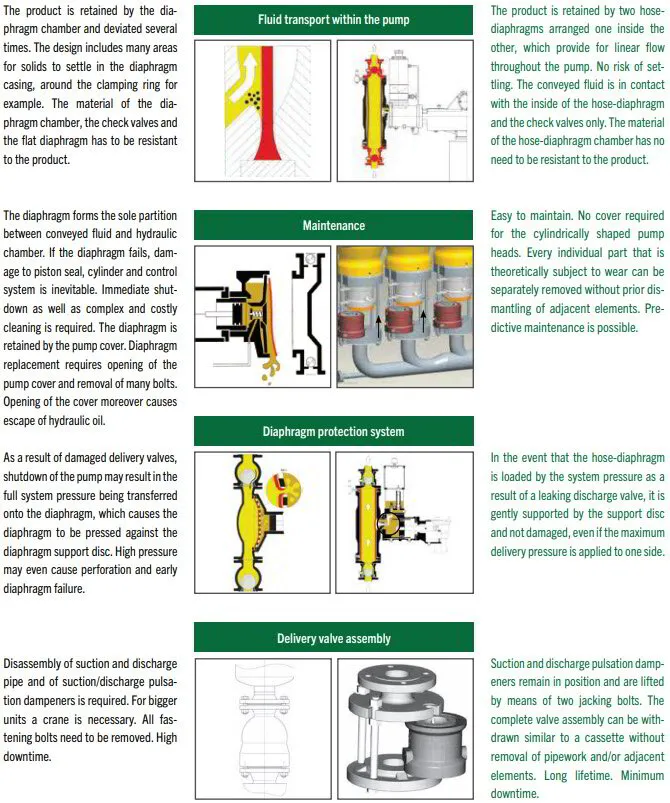
For a long time, diaphragm pumps or diaphragm piston pumps have been used for the handling of media in industrial applications. Internal parts of such pumps (diaphragm housing and pump cover for example) are in direct contact with the conveyed fluid so that in many cases (especially when handling corrosive slurries) expensive construction materials are required that are chemically resistant to the conveyed fluid. In addition, failure of single diaphragms results in damage to the hydraulic end of the pump (pistons, cylinder liners, etc.) and high cost for wear parts and downtime. Diaphragm condition monitoring requires elaborate and sensitive conductivity measurement systems in the hydraulic chamber.
Hose diaphragm piston pumps
In order to avoid the disadvantages of traditional diaphragm pumps, FELUWA has developed its hermetically sealed, leakproof, reciprocating displacement pump, the aptly named hose diaphragm piston pump. This pump has been successfully operated in worldwide applications for more than 40 years. It is characterised by an extraordinarily high technical and economic value. With the FELUWA hose diaphragm piston pump, the commonly utilised principle of a flat diaphragm has been extended by the additional provision of a flexible hose-diaphragm so that the conveyed fluid is in direct contact with the inside of the hose-diaphragm and check valves only. Wet end and drive end of the pump are separated by a flat diaphragm and a hose-diaphragm.
The second actuation fluid between flat and hose-diaphragm serves as hydraulic coupling and safety aid for leak detection. A mechanical valve system in the hydraulic chamber ensures automatic control and compensation of the actuation fluid volume without additional oil pump and control unit.
Even in the event of a hose-diaphragm failure, the secondary diaphragm ensures that the slurry will not enter the hydraulic drive end so that operation can be maintained. This contributes to low costs for wear parts and high availability.
MULTISAFE® double hose-diaphragm pumps
Although hose diaphragm piston pumps already represent a significant technical innovation with several thousand units being well proven, consistent further development has been pursued with the MUL- TISAFE® double hose-diaphragm process and transportation pump. Basically, it is a hermetically sealed, leak-proof, oscillating displacement pump with double sealing of the wet end from the hydraulic drive end and the environment by means of two hose-diaphragms which are arranged one inside the other. The flat diaphragm is fully abandoned.
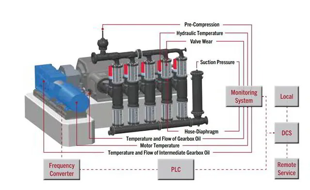
MULTISAFE® pumps utilise an overall diagnostic system for permanent condition monitoring of primary and secondary hose- diaphragms (by means of pressure sensors), check valves (FELUWA Valve Performance Monitoring System – FVPMS), suction pressure as well as hydraulic and gearbox oil temperature. Double hose-diaphragm pumps are characterised by unique design features and advantages, which are de- scribed in detail in this brochure and put this pump ahead of any other diaphragm pump design.
Working Principle and Safety
Working Principle Of MULTISAFE® Pumps
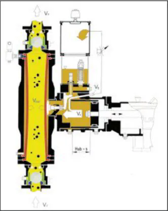
The rotary driving motion of the pump gearbox is converted into a reciprocating action of the crosshead by means of the crank drive. The crosshead is connected to the piston or plunger, respectively. By means of hydraulic fluid the piston actuates a pair of redundant hose-diaphragms, which are arranged one inside the other. They not only enclose the conveyed fluid in a linear flow path, but also provide double hermetic sealing from the hydraulic drive end. The conveyed fluid will neither come in contact with the pump head nor with the hydraulic area. For general process engineering applications, the hydraulic flu- id normally consists of hydraulic oil. As an alternative option, non-compressible fluids with physiologically harmless lubricants are applied, which are compatible with the conveyed fluid.
Pumping action is affected by displacement of the inside volume resulting from contraction of the hose-diaphragms. Unlike so-called peristaltic hose pumps with mechanical drive, the hose-diaphragms of the MULTISAFE® pump are not squeezed. In step with the piston stroke, they are only subject to pulsating action, comparable with that of a human vein. Elastic distortion of the hose-diaphragms is path-controlled and effected in a concentric manner due to their inherent construction. As a result of hydraulic support, the hose-diaphragms are subject to little load even under high working pressures. The service life of hose-diaphragms is considerably extended beyond that of traditional flat diaphragms which reflects in very good MTBF (Mean Time Be- tween Failure) and MTBR (Mean Time Be- tween Repair) values. The optimised pump head design with reduced dead space and linear flow path allows for the achievement of highest efficiencies
Working Principle and Safety
High Operating Safety
One of the distinct advantages of the MUL- TISAFE® pump is its linear flow path without deviation, so that it is especially conducive to the handling of shear-sensitive, aggressive, abrasive and solids carrying fluids and slurries, even at high viscosity. Unlike traditional diaphragm pumps, hose-diaphragms do not require a clamping ring that allows for settling of solids which results in early diaphragm failure.
The pump offers unique operating reliability. Even in the event that one of the hose diaphragms leaks or fails, the second hose- diaphragm will ensure that pump operation can be maintained until the next planned shutdown of the unit. Any internal loss of hydraulic fluid is automatically compensated by the incorporated high-precision mechanical leakage compensation valve. The leakage compensation system ensures stable, precise operating conditions. External compensation systems are not required. For each individual application the remaining medium-contacted components are subject to tailored material combinations in coordination with the client. In terms of the selection of suitable materials under consideration of the fluid characteristics FELUWA can rely on decades’ worth of experience.
FELUWA Stroke and Reduction Gearboxes and Crank Drives
The conversion of the rotary motion of the motor output shaft into a reduced axial reciprocating action of the pump piston or plunger is achieved by powerful combined FELUWA stroke and reduction gearboxes or by a combination of FELUWA crank drives with separate gear units. Both drives are available in various ratings for a maximum power transmission of 3,500 kW. Design and development of these units are based on high reliability and long service life.
Fabrication, assembly and factory performance tests are carried out by a well-educated and trained expert team. Innovative fabrication and machining methods, proven material qualities and calculation systems for component and design strength ensure that customers may rely on high availability even under the most arduous of conditions. In order to offer maximum safety, finite element method (FEM) is applied for dimensioning and design.
All bearings of driving and crank shafts are designed as large antifriction bearings with an expected service life of 100,000 hours plus. All crank shafts of our crank drives are made of forged raw mate- rial to ensure highest operating safety and performance.
Drive options:
Electric motors
for stationary operation
• Asynchronous three-phase
current motors
• Flameproof enclosure (Ex) acc. to ATEX
• Low or medium voltage
Variable frequency drives
• Low or medium voltage
Internal combustion engines
for mobile applications
• Diesel engines
• Petrol engines
Static displacement drives
for existing hydraulic systems
• Stationary and mobile application
• Fluid power motors
Special solutions available
FELUWA Check Valve Design Options
Check valves rank among the key com- ponents of oscillating displacement pumps.
With FELUWA MULTISAFE® double hose-diaphragm pumps and hose diaphragm piston pumps, the suction and dis- charge check valves are to be considered as the sole real wearing parts. For this reason, the achievement of utmost lifetime is paramount for valve design.
By means of the latest CFD methods FELUWA check valves are individually adapted to the application, both with regard to flow velocity and the selection of material and flow geometry.
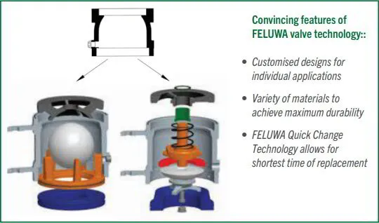
Depending on the application, the check valves are either carried out as single or double ball, cone or plate valves.
Quick Change Device for Check Valves
FELUWA MULTISAFE® double hose-diaphragm pumps are typically characterised by easily removable check valves of wafer design. This valve design not only ensures linear flow path throughout the pump and valves.
By means of jacking bolts it also allows for easy withdrawal of the complete valve assembly like a cassette without prior removal of adjacent elements. In order to facilitate maintenance, bigger valves from design size 137 are designed with a swivel- ling style holder. Removal neither requires specialised staff nor special tools.
Big size valves are additionally provided with the patented FELUWA Quick Change System, which allows for replacement of the inner valve parts without previous removal of adjacent components or piping in less than 30 minutes. The valves are subject to hydraulic fixing only. For maintenance, opening and closing are effected by means of a hand pump, which permits minimum downtime for maintenance and guarantees maximum availability.
Double Valves
Double valves are specified for media with high levels of impurities and applications which require a particularly continuous flow (e.g. gasifier feed pumps in coal gasification systems).
If a particle gets jammed in one of the valves for a short period of time, the second valve ensures effective sealing, thus preventing medium backflow and a resulting loss of volume.
Control Systems of MULTISAFE® Double Hose-Diaphragm Pumps and Hose Diaphragm Piston Pumps
Condition monitoring of hose-diaphragm clamping
Particularly when it comes to the handling of toxic or other fluids that are harmful to the environment or to aseptic process engineering applications, condition monitoring of diaphragms has to be extended to the clamping area.
For this reason, a unique and redundant diaphragm clamping system has been developed for MULTISAFE® double hose- diaphragm process pumps. It allows for permanent monitoring of the clamping area and reliable prevention of leaks.
Elastic distortion of hose-diaphragms is path-controlled and effected in a concentric
manner due to their inherent construction. The space between both hose-diaphragms is unpressurised and ends in a central transfer point. In the event that one of the hose-diaphragms leaks or fails, either product or hydraulic fluid will penetrate into the unpressurised intermediate space.
The resulting build-up of pressure is automatically fed to the hose-diaphragm condition monitoring system and activates the respective electrical contactor pressure sensor, which sends an alarm signal.
Any variation of pressure can furthermore be indicated by means of an integrated pressure gauge or a combination of pressure gauge and signal transmitter. Since the pump is fully functional with a single hose- diaphragm, pump operation can be maintained until the next scheduled shutdown even if one of both hose-diaphragms is leaking.
Acoustic Valve Diagnostics For Early Recognition Of Wear In Delivery Valves
FELUWA Valve Performance Monitoring System (FVPMS)
For early recognition of wear in delivery valves, FELUWA has developed specific diagnostic equipment.
The measuring principle is capable of detecting leaks, even if the loss of output is still less than 1.5 %.
By means of the FVPMS diagnostic system, the operational safety and availability of pumps is significantly increased, since wear is precisely localised and detected at an early stage, which allows for specific forward planning of service and repair.
Mechanical Leakage Control
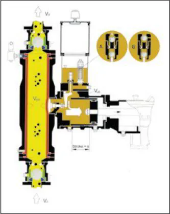
Loss of hydraulic fluid (VL, VÜ, VB) is automatically compensated by FELUWA pumps. For these situations the pumps are provided with a unique mechanical leakage control and compensation device within the hydraulic chamber. This system operates fully automatically, neither requires a separate oil pump nor a control system and is more- over not subject to wear.
During the suction stroke, the diaphragm (either hose-diaphragm or flat diaphragm, depending on the pump type) is drawn to- wards the hydraulic chamber of the piston or plunger. If the hydraulic oil volume de- creases due to leakage at the piston/plunger seal, the diaphragm will actuate a control disc, which in turn opens the compensation valve via a lever. Further backward movement of the piston/plunger causes a vacuum in the actuation chamber, since the diaphragm cannot move any further. As soon as the vacuum exceeds the setting range of the compensating valve (make-up valve), the valve opens. The actuation fluid (VL, VÜ, VB) that had been displaced into the oil reservoir during the delivery stroke is replenished during the increased suction stroke. By this means, the missing volume of hydraulic flu- id (VLE) is replaced in the hydraulic chamber. Since the compensating valve cannot open unless the leakage control valve is mechanically opened by a lever, it is ensured that the diaphragms cannot be overstretched.
Pressure Relief Valve
Each pump head is provided with an in- dividual, easily accessible pressure relief valve in the hydraulic fluid. This valve is set to the exact nominal pressure required during the works test run of the pump. If an over-pressure situation becomes evident in the hydraulic fluid, i.e. due to a closed dis- charge sluice valve, the pressure relief valve will open, thus relieving hydraulic fluid (VÜ) into the hydraulic oil reservoir. From this reservoir the oil is automatically returned into the pump chamber via the leakage compensation valve. The relief valve protects the pump as well as the gearbox from overload which may arise from an erroneously closed isolating valve or from a blocked discharge pipe etc.
Pressure relief valves are also available with type approval and with lead seal.
Bypass Flow Control
A bypass system which functions in the same manner as the pressure relief valve is fitted to the pump as an option for short- term flow control. Essentially, with each delivery stroke of the pump, an infinitely adjustable portion of the hydraulic oil (VB) displaced by the piston/plunger is diverted into the hydraulic oil reservoir. Since the volume being displaced by the piston/plunger onto the diaphragm (either hose-diaphragm or flat diaphragm, depending on the pump type) is reduced by the volume being diver- ted into the hydraulic oil reservoir, the out- put of the pump decreases accordingly.
The bypass control is only designed for a relatively low driving power up to 5.5 kW or for short-term control (e.g. during system startup). Alternatively, brief opening of the bypass valve during pump startup generally enables relatively rapid bleeding and diaphragm positioning in line with the design.
Pulsation Dampening
Atypical characteristic of oscillating displacement pumps is the hydro-dynamic independency of the delivery flow from the pressure and vice versa. The reason for this feature is due to the mechanics of pressure generation by means of a displacement piston which prevents backflow and thus an escape of the displaced volume into the pipework.
This principle allows for the achievement of extraordinarily high hydraulic efficiencies of up to 96%. Conversely, the oscillating movement causes undesirable flow fluctuations and pressure pulsations. In order to ensure high efficiency of pulsation dampeners, the volume of moved liquid columns has to be kept as low as practicable.
For this reason, pulsation dampeners are always located close to the pump heads, i.e.
Directly above the discharge valves or below the suction valves, respectively.
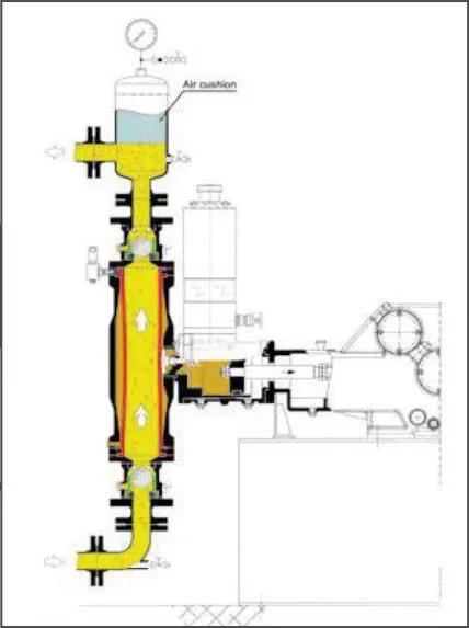
To avoid pressure pulsations, an array of different pulsation dampeners is employed. Dependent on the actual working conditions, traditional pulsation dampeners (pressure air vessels) with air or gas cushion or so-called hose-diaphragm pulsation dampeners (PULSORBER) with nitrogen-filled accumulators are applied.
Air vessels
With traditional pressure air vessels, the gas cushion is held directly above the conveyed fluid. Under peak pressures and/or excessive flow, this cushion is compressed above the fluid level and released during the suction stroke of the pump. The fluid is then displaced into the discharge pipe and mini- mises pulsations accordingly. Since there is no separation between gas cushion and medium, air vessels are mostly only used for low pressure applications or at the suction side.
Air Vessels and In-Built Piston Compressors
In-built FELUWA piston compressor
When using standard air vessels or hose-diaphragm pulsation dampeners, the attainable residual pulsation depends on the com- pressed gas volume above the liquid column within the pressure vessel. With air vessels, however, there is a constant loss (solution) of gas at the contact surface of the conveyed fluid, which reduces the dampening volume accordingly. The compensation of this loss within the air vessel requires periodic refilling by means of costly monitoring and filling devices equipped with shut-off and control units.
For this purpose, FELUWA has developed an ingenious and most effective ‘’inbuilt piston compressor”.
With each piston stroke, it feeds a small quantity of gas or atmospheric air into the discharge air vessels. The attainable pressure of the pump piston compressor is always considerably higher than the maximum pump pressure. This ensures that the conveyed fluid cannot flow back to the pump piston compressor under normal working conditions.
Working principle
With each return stroke of the piston rod, a small volume of filtered air (or gas) is sucked into the compressor chamber via a valve. With the forward stroke of the piston rod this air volume is fed via the non-return valve into the air vessels. This procedure is repeated with each stroke of the pump and is only active when the pump is operating. By this means, costly starting and stopping of air injection devices is fully eliminated and the available air volume within the air vessels is always maintained at an optimum level. The attainable residual pulsation is reduced to a minimum. At high pressure and/ or applications which require frequent and fast filling of the air vessels, the suction end of the in-built piston compressor may additionally be fed by compressed air.
PULSORBER
Foroperatingpressuresintherangeof≥40 bar and products which do not allow for the contact of air or gas, considerably more efficient diaphragm pulsation dampeners are applied.
The FELUWA hose-diaphragm pulsation dampener PULSORBER consists of a hose-diaphragm pulsation dampener and a bladder-type accumulator. The newly developed and more flexible PULSORBER 900 is made up of a roller diaphragm accumulator, which is able to cover higher ranges of operating pressure. Both systems offer all the advantages of traditional air vessels.
With each discharge stroke the displaced volume that exceeds the average flow is stored within the attached, hermetically sealed nitrogen accumulator. The stored volume is then released during the suction stroke and thus compensates the inevitable flow fluctuations.
The accumulator is pre-charged to approx. 80 % of the operating pressure in order to guarantee maximum efficiency.
When operating at varying discharge pressures, pre-compression has to be adapted accordingly.
Diagnostic Systems
Efficient diagnostics for mechanical and plant engineering
FELUWA has developed unique diagnostic systems which allow for supervision of the most important parameters. As a consequence, operators benefit from predictive maintenance, increased availability of the pumps and reduced operating costs. Optional direct linking of the pump in standard configuration with the control room permits remote diagnostics as well as coordination of maintenance with the operating schedule.
Sensors
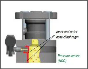
Diagnostics for hose-diaphragms: Hose-Diaphragm Guard (HDG)
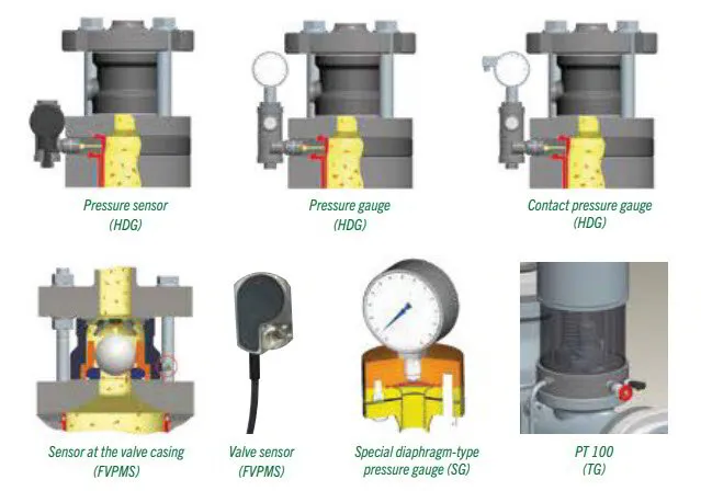
Whereas traditional diaphragm piston pumps require conductivity measurement systems, permanent condition monitoring of MULTISAFE® hose-diaphragms is ensured by means of pressure switches, pressure gauges or contact pressure gauges. In the event that one of the hose-diaphragms leaks or fails, either product or actuation fluid will penetrate into the unpressurised intermediate space. The resulting build-up of pressure is led to the condition monitoring system, which in turn immediately provides a signal with manifold processing options. Nevertheless, operation can be maintained with a single hose-diaphragm until the system allows for scheduled shutdown and repair.
Diagnostics for check valves:
FELUWA Valve Performance Monitoring System (FVPMS)
Permanent condition monitoring of individual check valves is effected by means of acoustic
sensors which are fixed to the outside of the valve casing. They are not in contact with the product and easily retrofittable. The sensor is capable of detecting leaks, even if the loss of output is still less than 1.5 %. By means of the FVPMS (FELUWA Valve Performance Monitoring System) diagnostic system, the operational safety and availability of pumps is significantly increased, since wear is precisely localised and detected at an early stage, which permits specific forward planning of service and repair. Furthermore, the system allows for partial replacement of the valve trims in dependence on the respective wear rate.
Diagnostics for suction pressure:
Suction Guard (SG)
Although MULTISAFE® pumps only require a low NPSHr value, unrestricted inlet of the conveyed medium is required in order to ensure proper pump operation. Supervision of the suction pressure if effected by a diaphragm pressure gauge specifically developed by FELUWA for slurry applications.
Diagnostics for hydraulic and gearbox oil temperature: TempGuard (TG)
Supervision of hydraulic and gearbox oil temperature is carried out by means of temperature sensors, optionally as PT 100, 4-20 mA signal or with HART communication protocol.
Pump Control Options
MULTISAFE® double hose-diaphragm pumps are designed to avoid sudden deviation from admissible working conditions and unplanned downtime. For additional backup of failsafe characteristics, MULTISAFE® pumps utilise an overall diagnostic system for permanent condition monitoring of essential components and parameters. The readings are saved with trend and allow for complete backtracking of the history over several weeks.
Basic
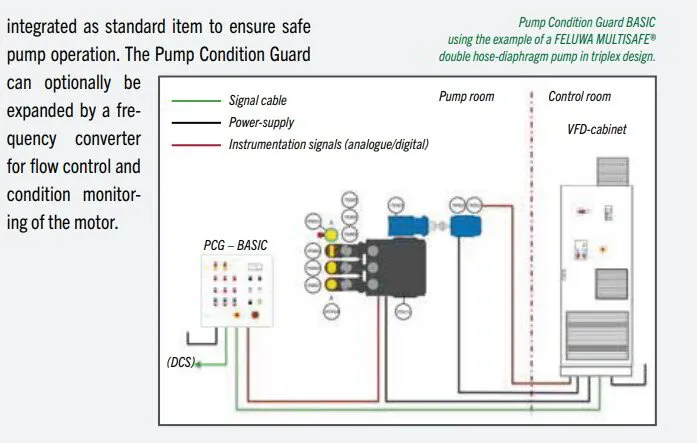
Pump Condition Guard BASIC Control and monitoring system for FELUWA MULTISAFE® pumps
Pump Condition Guard BASIC is a control, diagnostic and monitoring system developed for FELUWA MULTISAFE® double hose-diaphragm pumps. It allows for local (LCP) pump control (starting and stopping) and monitoring of the operating conditions by means of the sensors applied to the pump. Optional link to the client’s control system (hard-wired).
All pre-setting’s such as interlocks, alarms, error messages and shutdown conditions are integrated as standard item to ensure safe pump operation. The Pump Condition Guard can optionally be expanded by a frequency converter for flow control and condition monitoring of the motor.
Smart
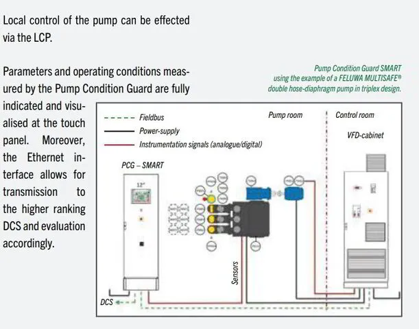
Pump Condition Guard SMART Control and monitoring system for FELUWA MULTISAFE® pumps
The Pump Condition Guard SMART refers to an extension of the control, diagnostics and monitoring system “Pump Condition Guard BASIC“ that has been especially developed for FELUWA MULTISAFE® double hose-diaphragm pumps. In addition to the BASIC version, the SMART version allows for communication with the local control system by means of PROFINET connection, for example. Via an Ethernet interface the higher ranking DCS can be connected to the local control system (LCP) so that signals for starting and stopping or flow variation can be implemented by the integrated PLC.
Local control of the pump can be effected via the LCP.
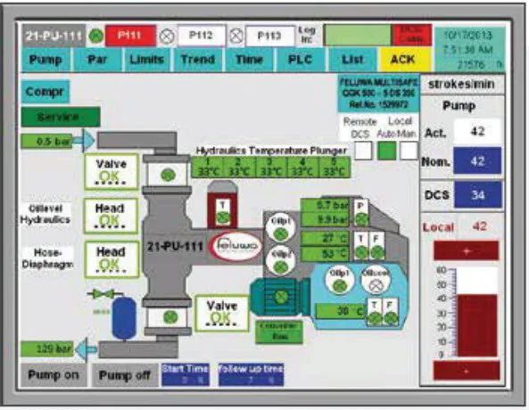
Parameters and operating conditions measured by the Pump Condition Guard are fully indicated and visualised at the touch panel. Moreover, the Ethernet interface allows for transmission to the higher ranking DCS and evaluation accordingly.
Touch Panels
For early detection of faults and with the objective of ensuring maximum availability, FELUWA supports the redundant nature of MULTISAFE® double hose-diaphragm pumps by means of an overall diagnostic system. Touch panels, which are integrated into the control cabinet, give the pump a transparent character and provide the operator with information on current operating parameters and the condition of fundamental parts. Bus systems link the touch panel to local process control, whereby Ethernet provides best conditions for communication and control of system frequency converters, PLC, touch panels and the FVPMS (FELUWA Valve Performance Monitoring System).
The pump can either be controlled via the frequency converter panel, the FELU- WA touch panel of the local control or via client’s DCS system with setpoint setting (via analogue input 4 to 20 mA). Touch panels provide time-related recording and direct or remote insight into check valves (via FVPMS), primary and secondary hose-diaphragms (via HDG), suction and discharge pressure (via SG and transducer), hydraulic and gearbox oil temperature (via TG), stroke rate, pre-compression of accumulators as a part of pulsation dampeners, oil lube systems of crank drive and intermediate gear (including temperature, pressure and flow), motor (including measurement of torque, absorbed power and FELUWA pump speed), transformer and frequency converter (variable frequency drive).
FelWebGuard
The Tailored Remote Maintenance Tool
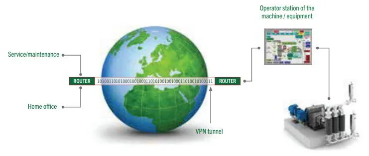
The FelWebGuard (FWG) system allows for remote PC access to the control unit of the pump, which enables the operator to access the control unit via the Internet and view all the current data. In addition, a safe, bidirectional VPN conduit can be set up for remote access to the control unit. All data and trends can be checked on a web inter- face, so that the planning of maintenance and smaller issues can be solved by remote action.
The system is linked to the Internet. In the event that actual values differ from programmed nominal values, the system will email an according notification to a FELUWA service technician. The system not only allows for higher availability and productivity, but also for a reduction in service costs.
The Internet – medium for data transport: In times of “Industry 4.0” FELUWA increasingly focuses on wireless data communication and the users benefit from the new prospects resulting thereof.
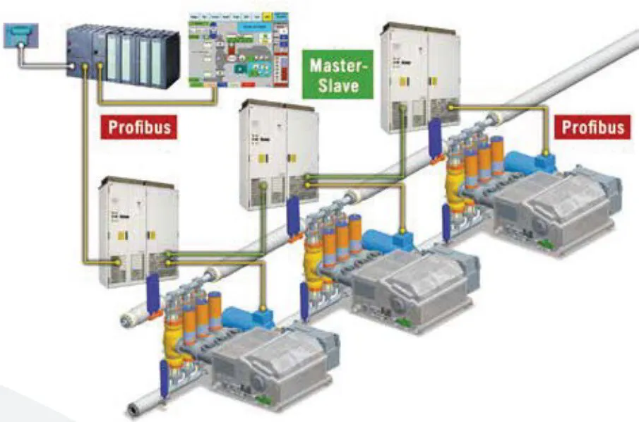
Pump Synchronisation
If multiple pumps are being operated in parallel and are discharging into the same piping, intelligent electronic crank shaft coupling helps optimising phase shifting of the pumps. Residual pulsation can thus be reduced to a minimum.
The advantage of pump synchronisation for plants is obvious: Not only the pump itself is protected, but all downstream equipment accordingly. Thanks to the resulting reduction of life cycle costs, operation of the whole plant will become more efficient and economic.
One pump serves as master pump. The control unit calculates and controls the required phase shifting depending on the number of pumps.
Pump synchronisation requires a control unit, a frequency converter and a transmitter system to determine the crank angle for each of the pumps.
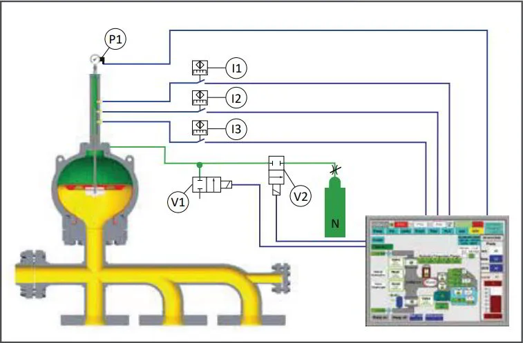
PULSATROL 900
In comparison to typical bladder-type accumulators, the FELUWA PULSATROL 900
With roller diaphragm accumulator offers a unique advantage: The nitrogen cushion is automatically and individually adapted to the operating conditions by means of the Pump Condition Guard SMART. The position of the roller diaphragm is detected by an inductive transmitter. Based on this position, a coefficient of operating pressure and precompression can be calculated. By means of this index number the control unit is able to determine whether increase or decrease of the pre-compression and filling (V2) or bleeding (V1) of nitrogen is required.
The FELUWA PULSATROL is, therefore, not sensitive to operating conditions which deviate from the design layout and allows for a reduction of the uniformity coefficient to less than 0.5 % (p to p).
DownFlow Technology (DFT)
Pumping of heterogeneous mixtures and fluids containing coarse contaminations calls for custom-tailored solutions to ensure permanently trouble-free operation.
With traditional diaphragm pumps there is the risk of excessive stretching of the diaphragm in the pump head or suction valve due to sedimentation so that it may even be pressed into the discharge check valve, which inevitably results in diaphragm failure.
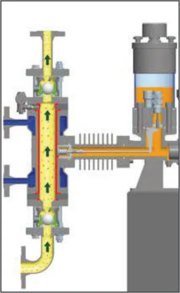
In order to avoid disadvantageous sedimentation, MULTISAFE® double hose-diaphragm pumps literally turn the traditional pumping principle upside down, which means a flow from the top to the bottom (Fig. 1). The cylindrical shape of the diaphragm with maxi- mum linear flow lines panders to the flow behaviour and avoids the settling of solids.
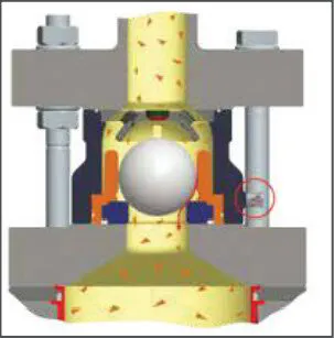
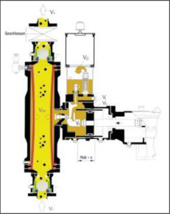
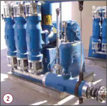
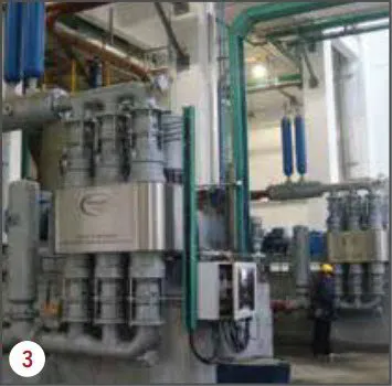
Handling of fluids carrying large solids more- over requires special and custom-tailored check valves. Various design options, which assist the passage of coarse solids carried by the fluid, are available for downflow con- figuration, such as spring-loaded ball valves, spherical cap ball valves or special floating ball valves (Fig. 2). In case of critical process conditions, in which the continuous flow must by no means be interrupted, double valves in cassette design avoid backflow leaks resulting from jammed solids (Fig. 3).
Special Designs of MULTISAFE® Double Hose-Diaphragm Process Pumps
Fluids in aseptic process technology re- quire pumps which provide maximum cleanliness and biological safety. FELUWA MULTISAFE® double hose-diaphragm pro- cess pumps in aseptic design meet the necessary purity criteria and FDA regulations in terms of fluid-contacted materials. Designs with EHEDG conformity are available upon request.
Some media require a minimum temperature if they are to retain their positive flow characteristics. In the event of a temperature drop, they will become very viscous, solidify or crystallise. Also in terms of extreme pumping temperatures the modular system of double hose-diaphragms includes a great variety of options, such as
• Designs with ribbed casing area (convector)
• Designs with cooling or heating jacket
• Designs with double hose-diaphragms and additional flat diaphragm
Conveyed media with entrained gas or air must be compressed during the pumping action in order to avoid a loss in flow rate. By means of a so-called dead space reducing cylinder in the hose-diaphragm, the volume of the fluid chamber is reduced to minimum. Thus, entrapped gas bubbles are automatically compressed and the hydraulic efficiency of the pump is optimised.
Quintuplex Design of MULTISAFE®
Double Hose-Diaphragm Pumps
Worldwide unique configuration
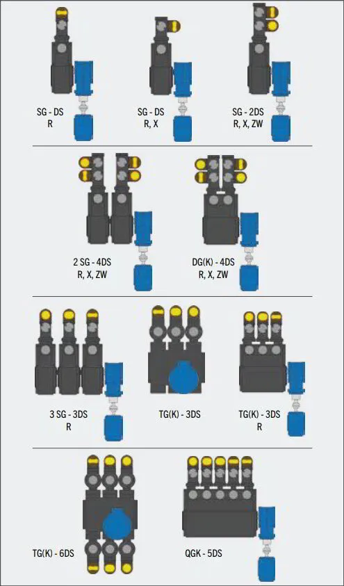
MULTISAFE® double hose-diaphragm pumps are designed with relatively narrow cylindrically shaped pump heads when compared to standard diaphragm piston pumps and therefore allow for the arrangement of five pump heads in parallel. When considering high flow and pressure rates, quintuplex design would not be economical for traditional diaphragm piston pumps, because circular flat diaphragms would require a gearbox design that would be excessively wide to accommodate the size of the heads in parallel.
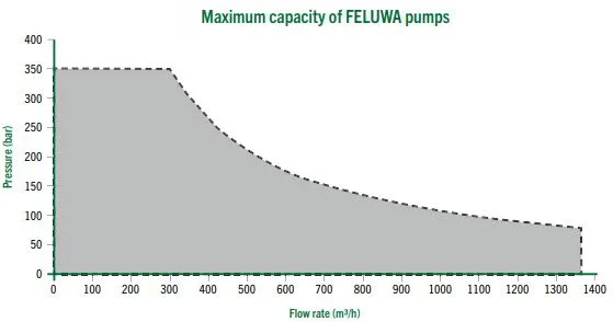
Quintuplex configuration of FELUWA MULTISAFE pumps offers unprecedented uniformity. Even without provision of pulsation dampeners, residual pulsation is reduced to 5.1 % p to p. Quintuplex pumps are available with three different crank drive options and allow for flow rates of up to 1,350 m3/h and pressures of up to 350 bar.
Quality
Made In Germany
Quality management
Fabrication of FELUWA process and transportation pumps, air vessels and pulsation dampeners is subject to a comprehensive and efficient quality programme that is adapted to actual requirements. The quality and environmental management system is in accordance with DIN EN ISO 9001:2015 and 14001:2015 standards. FELUWA is moreover certified according to the QA system (Module H) of Directive 2014/68/ EU and was granted the EAC Certificate for exports to the Eurasian Economic Union.
Pump testing facilities
In the course of mechanical fabrication and testing on FELUWA’s state-of-the-art performance test rigs, all important pump characteristics and components are determined and documented by test reports.
Test procedures – Pump test rig
• Measurement of displacement pumps according to VDMA 24284
• Hydrostatic pressure test
• Flow measurement at specified pressure and number of strokes
• Determination of sound power and sound energy levels
• Absorbed power
Test procedures – Fabrication
• Dimensional check against fabrication drawings
• Spring and hardness test
• Brinell measurement system • Coating thickness according to DIN EN ISO 2178.
Measuring Facility
• Actual-theoretical comparison with an accuracy of +/- 0.016 mm
ATEX
All FELUWA pumps are optionally avail- able in ATEX-compliant design according to Directive 2014/34/EU of the European Parliament and of the Council.
Fully automatic pump test rig
Before shipment, all pumps are subject to a rigorous test regime. The test rig system forms a crosspoint where all process para- meters (discharge pressure, flow rate, stroke rate, absorbed power etc.) merge and are indicated and recorded in real-time.
Moreover, pump parameters can be set to requested values, e.g. the flow rate by variation of the stroke rate and the discharge pressure by an electrical control valve. After completion of the test run, all resulting data are exported into a test report in accordance with international standards.
Technical centre
FELUWA disposes of comprehensive means for testing of conveyed media and its be- haviour during the pumping procedure. In the technical centre FELUWA carries out rheological tests to determine specific characteristics of the product, such as density and behaviour in terms of sedimentation or wear. Tests are supported by a test rig that is specified for mixtures of fluid and solids in a flow range of up to 14 m3/h and pressures up to 250 bar. Such tests provide valuable in- formation concerning the extended service life of wear parts, for example.
Key Applications
FELUWA process and transportation pumps are specified for a great variety of industries, such as power, metallurgical, mining, chemical, petrochemical, pharmaceutical, cement, ceramic and process engineering.
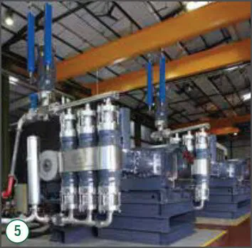
1. Ash disposal
In coal-fired power stations, large volumes of fly and bottom ash are generated as a result of the incineration process. Disposal of this dense ash to the relating ash ponds is effected by pipeline transportation.
FELUWA pumps are capable of handling large solids so that even bottom ash slurry can be reliably pumped over long distances.
2. Autoclave feeding
In coal-fired power stations, large volumes of fly and bottom ash are generated as a result of the incineration process. Disposal of this dense ash to the relating ash ponds is effected by pipeline transportation.
FELUWA pumps are capable of handling large solids so that even bottom ash slurry can be reliably pumped over long distances.
3. Coal gasification
In coal-fired power stations, large volumes of fly and bottom ash are generated as a result of the incineration process. Disposal of this dense ash to the relating ash ponds is effected by pipeline transportation.
FELUWA pumps are capable of handling large solids so that even bottom ash slurry can be reliably pumped over long distances.
4. Digester feeding
In coal-fired power stations, large volumes of fly and bottom ash are generated as a result of the incineration process. Disposal of this dense ash to the relating ash ponds is effected by pipeline transportation.
FELUWA pumps are capable of handling large solids so that even bottom ash slurry can be reliably pumped over long distances.
5. Mine dewatering
In coal-fired power stations, large volumes of fly and bottom ash are generated as a result of the incineration process. Disposal of this dense ash to the relating ash ponds is effected by pipeline transportation.
FELUWA pumps are capable of handling large solids so that even bottom ash slurry can be reliably pumped over long distances.
6. Pipeline transfer
In coal-fired power stations, large volumes of fly and bottom ash are generated as a result of the incineration process. Disposal of this dense ash to the relating ash ponds is effected by pipeline transportation.
FELUWA pumps are capable of handling large solids so that even bottom ash slurry can be reliably pumped over long distances.
7. Spray dryer feeding
In coal-fired power stations, large volumes of fly and bottom ash are generated as a result of the incineration process. Disposal of this dense ash to the relating ash ponds is effected by pipeline transportation.
FELUWA pumps are capable of handling large solids so that even bottom ash slurry can be reliably pumped over long distances.
8. Tailings transfer
In coal-fired power stations, large volumes of fly and bottom ash are generated as a result of the incineration process. Disposal of this dense ash to the relating ash ponds is effected by pipeline transportation.
FELUWA pumps are capable of handling large solids so that even bottom ash slurry can be reliably pumped over long distances.
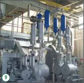
9. Wet Oxidation – Reactor Feeding
In coal-fired power stations, large volumes of fly and bottom ash are generated as a result of the incineration process. Disposal of this dense ash to the relating ash ponds is effected by pipeline transportation.
FELUWA pumps are capable of handling large solids so that even bottom ash slurry can be reliably pumped over long distances.
Hose Diaphragm Pumps
Our Team
FELUWA Service Team
The FELUWA service team ensures that the pumps operate at maximum efficiency and availability and enjoy maximum service life
Installation
Our engineers are available to help customers install FELUWA pumps worldwide. We can advise customers at every stage of the process: beginning at the installation planning stage, right up to the actual on-site installation of the pump.
Training
At FELUWA, we offer our customers a comprehensive training programme, tailored to their individual needs. We provide a combination of theoretical and practical elements at our training centres, workshops, or at the customer’s location on site. This allows our clients to benefit from modules which have been tailored to their needs and the needs of their operating personnel.
Service/Maintenance
At FELUWA, we offer our customers the added value of systematic planning of storing spare parts in anticipation of any possible need as well as planning and implementation of regular maintenance. Regular expert maintenance guarantees a long working life of the pump systems and their components.
Our engineers are at your disposal and offer rapid service. Precise planning and preparation is necessary to keep pump downtime to the absolute minimum. Our comprehensively- stocked warehouse at the FELUWA plant in Mürlenbach facilitates the rapid delivery of original spare parts. The majority of our spare parts is available for shipment within 24 to 48 hours – even for pumps aged 30 years plus.
Commissioning
Our experienced experts at FELUWA put the pumps and equipment into operation and offer
the client’s on-site staff careful, comprehensive instruction for operating the pumps.
Customer Satisfaction
What Our Customers Are Saying
FELUWA pumps have been proving their high quality and efficiency all over the world for several decades.
Satisfied clients have confirmed the excellent availability and reliability of FELUWA pumps in numerous reference letters.
Minera Boleo – Mexico (MULTISAFE® QGK 500 – 5 DS 350)
" Boleo is very satisfied with the performance and reliability of these pumps. ... Hose-diaphragm lifetime is about 2 years. ... we are very satisfied with the aftersales service that FELUWA has provided over the last few years. "
Sinopec International Jinling – China (DG 250 – 4 SM 460)
"The operation of the pumps is normal, safe and reliable. ... simple and convenient installation and maintenance ... FELUWA's service engineers are professional"
ROMELECTRO – Romania (MULTISAFE® TGK 400 – 3 DS 230)
pumps are working to our entire satisfaction ... FELUWA pumps are extraordinarily reliable
ETI BAKIR A.Ș. – Turkey (MULTISAFE® TGK 250 – 3 DS 100)
"As a condition we may confirm that the FELUWA MULTISAFE pumps are extraordinarily reliable and that we would very likely use the pumps of this type again in case of any future requirements"
Shenhua International Ltd. – China (MULTISAFE® TGK 400 – 3 DS 230)

